Skip to: site menu | section menu | main content
MAJOR SERVICE OPERATIONS
Removing Third Member Assembly
To remove the third member from the truck it is necessary to split
the universal joint which is part of the front propeller shaft
assembly as follows :
Remove the two nuts holding the front propeller shaft assembly
to the cross member and drop the unit. Remove the cap screws
holding the ball collar to the housing and slide the ball back
on the rear axle propeller shaft housing. Remove the trunnion-bearing
lock rings or wires with a drift or other sharp pointed tool
by lifting them free from their slots. Drive the trunnion bearings
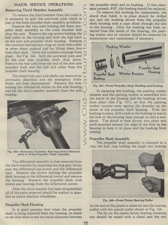
from place. See Fig. 164. Split the universal joint and let
the rear axle propeller shaft drop down. Remove the rear yoke
from the end of the rear axle propeller shaft and the ball
and collar from the propeller shaft housing.
The wheel hubs and axle shafts are removed as previously described
and the emergency brake shafts are then disconnected. Remove
the nuts holding the differential carrier to the axle housing
and lift the third member assembly from the axle housing.
Removing Trunnion Bearings from Universal
Joint in Front Propeller Shaft Assembly
The differential assembly is then removed from the third member
by removing the ring gear thrust pad, the differential cap screws
and the differential caps. Remove the screws holding the propeller
shaft housing to the differential carrier and remove the housing.
Remove the propeller shaft with pinion and bearings from the differential
carrier.
After the third member has been disassembled all of the parts removed
should be washed in gasoline to insure absolute cleanliness.
Propeller Shaft Housing
It is good practice that when the propeller shaft is being removed
from the housing, to check to see that there is not too much clearance
between
77the propeller shaft and its bushing. I f this clearance exceeds
.010", the bushing should be replaced.
To remove this bushing for replacement, the dowel that holds it
in place should be drilled out and the bushing driven from the
propeller shaft housing with a cape chisel through the slot in
the housing. After the bushing has been re-moved from the inside
of the housing, the packing washer and its retainer should be removed
for examination and replacement if necessary.
Fig. 165—Front Propeller Shaft Bushing and Packing
In replacing this bushing, the packing washer retainer and the
packing washer is assembled into the inside of the housing and
the bushing driven from place (See Fig. 165), so that the packing
washer retainer seats against the shoulder on the inside of the
propeller shaft housing. With the bushing in place, drill a hole
in the bushing to match the hole in the housing deep enough to
take a new dowel. The dowel is then driven into place and prick-punched
around the edge of the hole in the housing to keep it in place
and the bushing from turning.
Propeller Shaft Assembly
The propeller shaft assembly is clamped in a vise, the lock ring
holding the single row bearing
Fig. 166— Front Pinion Bearing Puller
on the end of the pinion is removed and the bearing pulled with
the special puller shown in Fig. 166.
The lip on the pinion thrust bearing retaining nut should be raised
with a chisel and the nut
Packing Washer
Propeller Shaft
Propeller Shaft Washer Retainer Housing Bushing
