Skip to: site menu | section menu | main content
If a 6.16 to 1 ring gear and pinion is installed in service, it is important that the differential carrier be marked as stated on the previous page.
Operation
The power is transmitted from the propeller shaft through the spiral drive pinion and drive gear to the differential and the axle shafts to the rear wheels. The differential gears permit one rear wheel to turn faster than the other, which condition exists when the truck is turning a corner. When the truck is traveling in a straight line and the rear wheel traction is equal on both wheels, the differential gears do not turn. The differential gears compensate for the twisting motion which would take place if the axle were a solid one-piece shaft from wheel to wheel and one wheel was forced to travel faster than the other.
Care
There is little that can be said about the care of a rear axle,
except that the oil level should be checked at regular intervals
by removing the filler plug in the axle housing cover and seeing
that the level is even with it.
The lubricant should be changed for climate changes, such as
summer and winter, and the proper grade added according to the
instructions under the chapter "General Lubrication."
It is a good plan to also check to see that the axle shaft nuts
or the nuts holding the rear wheels to the axle shafts are tight.
This little precaution will greatly pay for the small time that
it takes to do this operation.
Repair Operations
The repair operations on this truck type axle are divided into
two groups. One, the minor service operations, such as the removal
of the axle shafts, the replacement of brake drums, etc. These
operations are performed with the axle housing and third member
under the truck. Two major service operations, such as the replacement
of propeller shaft, ring gear and pinions, etc. These operations
are performed with the third member out from under the truck.
There are also two very important and essential points which
all service men must keep in mind when working on rear axles.
First— absolute
cleanliness must be observed, and second— factory limits
and clearances and specifications must be adhered to
75
MINOR SERVICE OPERATIONS To Remove and Replace Rear Wheel
To remove the rear wheel, remove the wheel hub nuts and remove
the wheel from the bolts which are attached to the wheel hub.
To replace the rear wheel, set the wheel on the bolts in the hub,
and assemble the hub nuts, tightening them down evenly on these
bolts until they are all tight.
To Remove and Replace Wheel Hub and Brake Drum
Remove the rear wheel as previously described. Remove the hub cap,
cotter pin, castle nut and
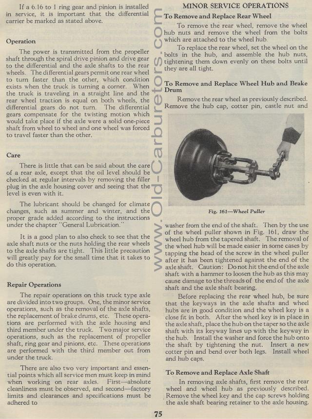
Fig. 161— Wheel Puller
washer from the end of the shaft. Then by the use of the wheel
puller shown in Fig. 161, draw the wheel hub from the tapered shaft.
The removal of the wheel hub will be made easier in some cases
by tapping the head of the screw in the wheel puller after it has
been tightened against the end of the axle shaft. Caution: Do not
hit the end of the axle shaft with a hammer to loosen the hub as
this may cause damage to the threads of the end of the axle shaft
and the axle shaft bearing.
Before replacing the rear wheel hub, be sure that the keyways in
the axle shafts and wheel hubs are in good condition and the wheel
key is a close fit in both. After the wheel key is in place in
the axle shaft, place the hub on the taper so the axle shaft with
its keyway lines up with the keyway in the hub. Install the washer
and force the hub onto the shaft by tightening the nut. Insert
a new cotter pin and bend over both legs. Install wheel and hub
caps.
To Remove and Replace Axle Shaft
In removing axle shafts, first remove the rear wheel and wheel
hub as previously described. Remove the wheel key and the cap
screws holding the axle shaft bearing retainer to the axle housing.
