Skip to: site menu | section menu | main content
and gaskets have an extra hole, the center one of the three that are closest together should be lined up with the notch in the hub flange of the axle shaft. There is an oil pocket in the oil deflector which should also be in line with the notch in the hub.
Wheel Hub and Brake Drum Peening Tool and Anvil
The brake drum should fit the shoulder of the axle shaft very closely. When the brake drum, gasket and oil deflector are in line as mentioned above, insert the six special bolts and force the heads down to the deflector. The end of the shoulder on the bolts should then be peened into the countersink around the bolt holes in the hub, using the anvil to support the bolt heads and the peening tool and anvil shown in Fig. 148, thus riveting these parts together.
MAJOR SERVICE OPERATIONS Removing Rear Axle Assembly
Raise the car from the floor by the use of jacks and car horses,
or by the use of a chain hoist and lifting device. Remove both
rear wheels. Disconnect all brake rods at the rear axle and the
shock absorber "I" bolts from the spring seats. Remove
the nuts and "U" bolts, holding the rear springs to the
spring seats. Disconnect the rear shackles and drop the springs.
Slide the axle back to disconnect the torque tube at the front
end which drops down to the floor. The axle is now free and can
be moved to the axle stand.
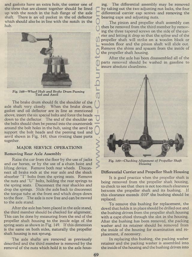
After the axle has been placed in the axle stand, the third member
should be checked for alignment. This can be done by measuring
from the end of the propeller shaft housing to the inside edge
of the spring seats as shown in Fig. 149. If this dimension is
the same on both sides, naturally the propeller shaft housing is
not sprung.
The axle shafts are removed as previously described and the third
member is removed by the removal of the nuts which hold it to the
axle housing. The differential assembly may be removed by taking
out the two adjusting nut locks, the four differential carrier
cap screws and removing the bearing caps and adjusting nuts.
The pinion and propeller shaft assembly can then be removed from
the third member by removing the three tapered screws on the side
of the carrier and letting it drop so that the spline end of the
propeller shaft will strike on a wooden block or wooden floor and
the pinion shaft will slide out. Remove the shims and spacers from
the inside of the propeller shaft housing.
After the axle has been disassembled all of the parts removed should
be washed in gasoline to insure absolute cleanliness.
Differential Carrier and Propeller Shaft Housing
It is good practice when the propeller shaft is being removed from
the propeller shaft housing, to check to see that there is not
too much clearance between the propeller shaft and its bushing.
If this clearance exceeds .010" the bushing should be replaced.
To remove this bushing for replacement, the dowel that holds it
in place should be drilled out and the bushing driven from the
propeller shaft housing with a cape chisel through the slot in
the housing. After the bushing has been removed, the packing washer
and its retainer should be removed from the inside of the housing
for examination and re-placement, if necessary.
In replacing this bushing, the packing washer retainer and the
packing washer is assembled into the inside of the housing and
the bushing driven into
MP'
Fig. 149— Checking Alignment of Propeller
Shaft Housing
