Skip to: site menu | section menu | main content
so the threads of the nuts fit into the threads of the differential
carrier. Install the bearing caps, making sure that the marks on
the caps line up with the marks on the carrier. It is good practice
to start the cap screws and then drop the cap onto the nut, using
the cap screws as a pilot.
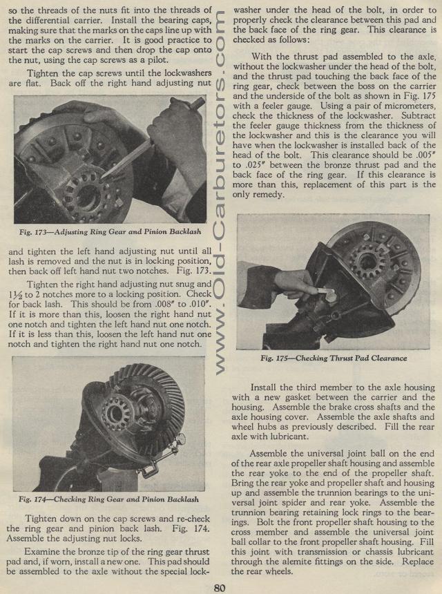
Tighten the cap screws until the lockwashers are flat. Back off the right hand
adjusting nut
Adjusting Ring Gear and Pinion Backlash
and tighten the left hand adjusting nut until all lash is removed
and the nut is in locking position, then back off left hand nut
two notches. Fig. 173.
Tighten the right hand adjusting nut snug and 1 % to 2 notches
more to a locking position. Check for back lash. This should be
from .008" to .010". I f it is more than this, loosen
the right hand nut one notch and tighten the left hand nut one
notch. If it is less than this, loosen the left hand nut one notch
and tighten the right hand nut one notch.
Fig. 174— Checking Ring Gear and Pinion Backlash
Tighten down on the cap screws and re-check the ring gear and
pinion back lash. Fig. 174. Assemble the adjusting nut locks.
Examine the bronze tip of the ring gear thrust pad and, if worn,
install a new one. This pad should be assembled to the axle without
the special lock-
80washer under the head of the bolt, in order to properly check
the clearance between this pad and the back face of the ring gear.
This clearance is checked as follows:
With the thrust pad assembled to the axle, without the lockwasher
under the head of the bolt, and the thrust pad touching the back
face of the ring gear, check between the boss on the carrier and
the underside of the bolt as shown in Fig. 175 with a feeler gauge.
Using a pair of micrometers, check the thickness of the lockwasher.
Subtract the feeler gauge thickness from the thickness of the lockwasher
and this is the clearance you will have when the lockwasher is
installed back of the head of the bolt. This clearance should be
.005" to .025" between the bronze thrust pad and the
back face of the ring gear. If this clearance is more than this,
replacement of this part is the only remedy.
Fig. 175— Checking Thrust Pad Clearance
Install the third member to the axle housing with a new gasket
between the carrier and the housing. Assemble the brake cross shafts
and the axle housing cover. Assemble the axle shafts and wheel
hubs as previously described. Fill the rear axle with lubricant.
Assemble the universal joint ball on the end of the rear axle propeller
shaft housing and assemble the rear yoke to the end of the propeller
shaft. Bring the rear yoke and propeller shaft and housing up and
assemble the trunnion bearings to the universal joint spider and
rear yoke. Assemble the trunnion bearing retaining lock rings to
the bearings. Bolt the front propeller shaft housing to the cross
member and assemble the universal joint ball collar to the front
propeller shaft housing. Fill this joint with transmission or chassis
lubricant through the alemite fittings on the side. Replace the
rear wheels.
