Skip to: site menu | section menu | main content
loosened. Cut off the rivet heads, which hold the pinion shaft to the coupling, and drive out the rivets. To remove the pinion and coupling from the propeller shaft, the press or special tool shown in Fig. 167 is necessary to prevent damage to the pinion and its bearing. In operation, one adapter is placed against the coupling and the propeller shaft threaded through the large steel block with the
Pinion and Coupling Removing Tools
large end away from the coupling. With the three special wedges placed in position around the shaft to hold it in the block (See Fig. 1(8), force the adapter and block apart by turning the nuts with the special wrench. This forces the pinion with the coupling assembled to it from the propeller shaft. Press the coupling from the pinion on an arbor press and press plates.
Clamp the spline end of the pinion in a vise with soft jaws and
remove the pinion bearing lock nut. Press the double row bearing
from the pinion shaft on an arbor press with the pinion bearing
remover.
Fig. 168— Removing Pinion and Coupling from
Propeller Shaft
After the bearings have been removed from the pinion, they should
be cleaned in gasoline and blown out with clean air. Oil the bearings
and rotate them by hand and check for excessive end play and roughness.
The single row bearing is manufactured with from .004" to
.006" end play. The double row bearing is of the pre-loaded
type, meaning that there is no perceptible looseness between the
balls and the raceways, when new, and can have a drag of .001" tightness
when either race
78is rotated by hand. If this bearing has any notice-able end play
it should be replaced, because this affects pinion depth adjustment.
To reassemble the propeller shaft assembly —press the double
row bearing onto the pinion shaft and assemble the lock nut. Draw
this nut up tight against the bearing and lock it in place in the
key-way of the shaft with a chisel.
The coupling is then pressed onto the pinion shaft so that the
hole in the pinion shaft and the hole in the coupling line up.
The pinion and coupling is then pressed on the propeller shaft
with the tool shown in Fig. 167, being sure that the rivet hole
in the coupling lines up with the rivet hole in the propeller shaft.
Insert the flat head rivets and rivet over the ends.
Fig. 169— Front Pinion Bearing Driver
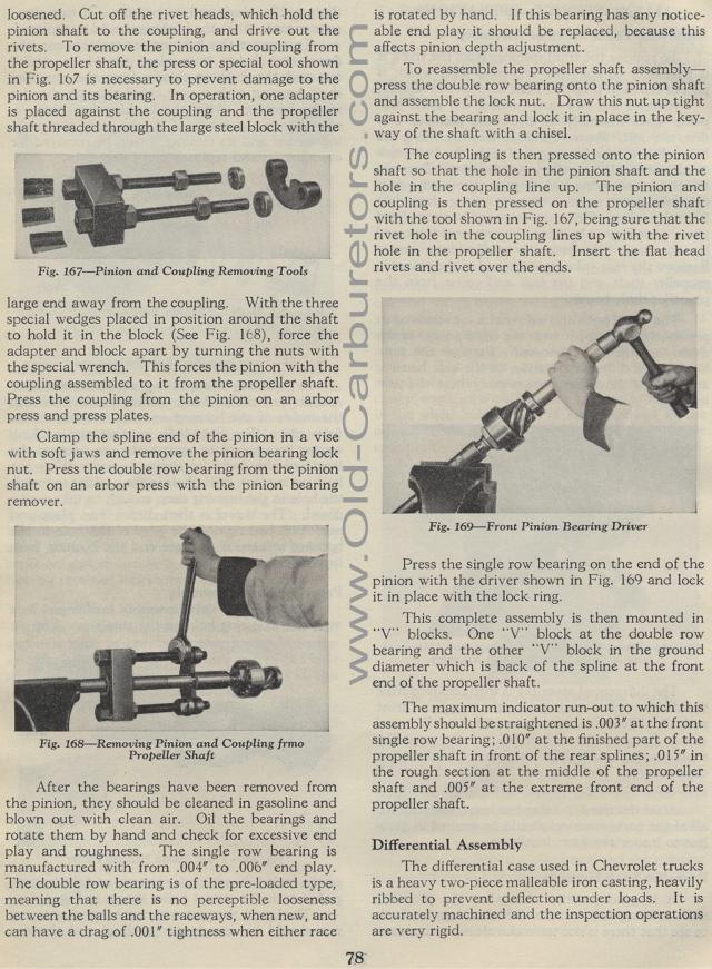
Press the single row bearing on the end of the pinion with the
driver shown in Fig. 169 and lock it in place with the lock ring.
This complete assembly is then mounted in "V" blocks.
One "V" block at the double row bearing and the other "V" block
in the ground diameter which is back of the spline at the front
end of the propeller shaft.
The maximum indicator run-out to which this assembly should be
straightened is .003" at the front single row bearing; .010" at
the finished part of the propeller shaft in front of the rear splines;
.015" in the rough section at the middle of the propeller
shaft and .005" at the extreme front end of the propeller
shaft.
Differential Assembly
The differential case used in Chevrolet trucks is a heavy two-piece
malleable iron casting, heavily ribbed to prevent deflection under
loads. It is accurately machined and the inspection operations
are very rigid.
