Skip to: site menu | section menu | main content
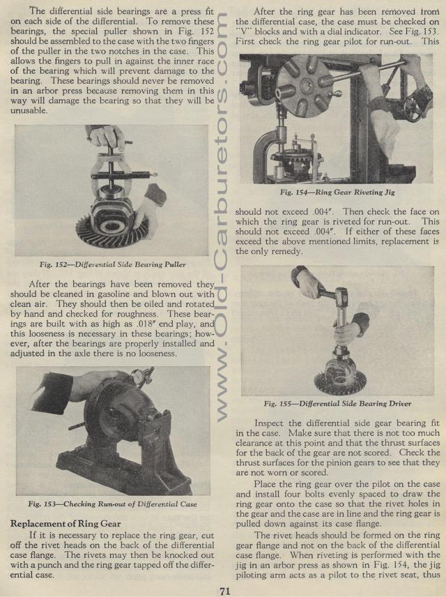
The differential side bearings are a press fit on each side of the differential. To remove these bearings, the special puller shown in Fig. 152 should be assembled to the case with the two fingers of the puller in the two notches in the case. This allows the fingers to pull in against the inner race of the bearing which will prevent damage to the bearing. These bearings should never be removed in an arbor press because removing them in this way will damage the bearing so that they will be unusable.
Differential Side Bearing Puller
After the bearings have been removed they should be cleaned in gasoline and blown out with clean air. They should then be oiled and rotated by hand and checked for roughness. These bearings are built with as high as .018" end play, and this looseness is necessary in these bearings; how-ever, after the bearings are properly installed and adjusted in the axle there is no looseness.
Fig. 153— Checking Run-out of Differential
Case Replacement of Ring Gear
If it is necessary to replace the ring gear, cut off the rivet
heads on the back of the differential case flange. The rivets may
then be knocked out with a punch and the ring gear tapped off the
differential case.
71
After the ring gear has been removed trorri the differential case,
the case must be checked on "V" blocks and with a dial
indicator. See Fig. 153. First check the ring gear pilot for run-out.
This
Fig. 154— Ring Gear Riveting Jig
should not exceed .004". Then check the face on which the
ring gear is riveted for run-out. This should not exceed .004".
I f either of these faces exceed the above mentioned limits, replacement
is the only remedy.
Fig. 155— Differential Side Bearing Driver
Inspect the differential side gear bearing fit in the case. Make
sure that there is not too much clearance at this point and that
the thrust surfaces for the back of the gear are not scored. Check
the thrust surfaces for the pinion gears to see that they are not
worn or scored.
Place the ring gear over the pilot on the case and install four
bolts evenly spaced to draw the ring gear onto the case so that
the rivet holes in the gear and the case are in line and the ring
gear is pulled down against its case flange.
The rivet heads should be formed on the ring gear flange and not
on the back of the differential case flange. When riveting is performed
with the jig in an arbor press as shown in Fig. 154, the jig piloting
arm acts as a pilot to the rivet seat, thus
