Skip to: site menu | section menu | main content
12th— Draw cutter bar "I" out of case, remove
front main bearing cap and take out front centering bushing "E."
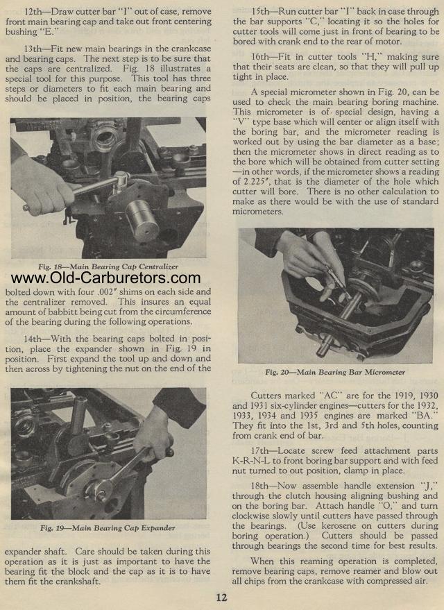
13th— Fit new main bearings in the crankcase and bearing caps. The next
step is to be sure that the caps are centralized. Fig. 18 illustrates a special
tool for this purpose. This tool has three steps or diameters to fit each main
bearing and should be placed in position, the bearing caps
Fig. 18— Main Bearing Cap Centralizer
bolted down with four .002" shims on each side and the centralizer
removed. This insures an equal amount of babbitt being cut from
the circumference of the bearing during the following operations.
14th— With the bearing caps bolted in position, place the
expander shown in Fig. 19 in position. First expand the tool up
and down and then across by tightening the nut on the end of the
Fig. 19— Main Bearing Cap Expander
expander shaft. Care should be taken during this operation as it
is just as important to have the bearing fit the block and the
cap as it is to have them fit the crankshaft.
12
15th— Run cutter bar "I" back in case through the
bar supports "C," locating it so the holes for cutter
tools will come just in front of bearing to be bored with crank
end to the rear of motor.
16th— Fit in cutter tools "H," making sure that
their seats are clean, so that they will pull up tight in place.
A special micrometer shown in Fig. 20, can be used to check the
main bearing boring machine. This micrometer is of special design,
having a "V" type base which will center or align itself
with the boring bar, and the micrometer reading is worked out by
using the bar diameter as a base; then the micrometer shows in
direct reading as to the bore which will be obtained from cutter
setting —in other words, if the micrometer shows a reading
of 2.225", that is the diameter of the hole which cutter will
bore. There is no other calculation to make as there would be with
the use of standard micrometers.
Fig. 20— Main Bearing Bar Micrometer
Cutters marked "AC" are for the 1919, 1930 and 1931 six-cylinder
engines — cutters for the 1932, 1933, 1934 and 1935 engines
are marked "BA." They fit into the 1st, 3rd and 5th holes,
counting from crank end of bar.
17th— Locate screw feed attachment parts K-R-N-L to front
boring bar support and with feed nut turned to out position, clamp
in place.
18th— Now assemble handle extension "J," through
the clutch housing aligning bushing and on the boring bar. Attach
handle "0," and turn clockwise slowly until cutters have
passed through the bearings. (Use kerosene on cutters during boring
operation.) Cutters should be passed through bearings the second
time for best results.
When this reaming operation is completed, remove bearing caps,
remove reamer and blow out all chips from the crankcase with compressed
air.