Skip to: site menu | section menu | main content
This should be from .004" to .011". Fig. 50. Cotter
pin nuts securely.
As a final and last check to be sure that the assembly will travel true with
the bore, check the
Fig. 50— Checking Connecting Rod End Clearance
clearance between the piston pin end of the connecting rod and the piston pin
bosses on the piston with a feeler gauge. This should not be less than .025".
Connecting Rod Dipper Height
The height of the connecting rod dipper is very important so that
the connecting rod bearings will get the proper amount of lubrication.
The oil trough depth gauge, illustrated in Fig. 51, is used to
check the distance of the oil dipper on the connecting rod from
the machined surface of the crankcase and also the distance between
the top edge of the small oil pan troughs in the oil pan to the
sides of the oil pan with all gaskets removed.
The rod in the center of the gauge is for checking the depth of
the oil troughs from the top of the pan.
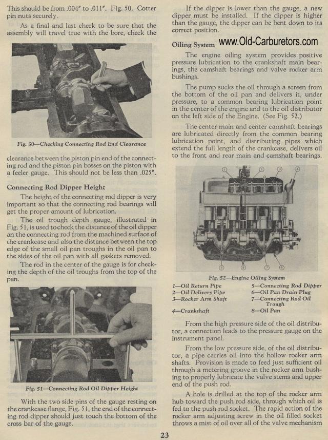
Fig. 51— Connecting Rod Oil Dipper Height
With the two side pins of the gauge resting on the crankcase flange,
Fig. 51, the end of the connecting rod dipper should just touch
the bottom of the cross bar of the gauge.
If the dipper is lower than the gauge, a new dipper must be installed.
If the dipper is higher than the gauge, the dipper can be bent
down to its correct position.
Oiling System
The engine oiling system provides positive pressure lubrication
to the crankshaft main bearings, the camshaft bearings and valve
rocker arm bushings.
The pump sucks the oil through a screen from the bottom of the
oil pan and delivers it, under pressure, to a common bearing lubrication
point in the center of the engine and to the oil distributor on
the left side of the Engine. (See Fig. 52.)
The center main and center camshaft bearings are lubricated directly
from the common bearing lubrication point, and distributing pipes
which extend the full length of the crankcase, delivers oil to
the front and rear main and camshaft bearings.
Fig. 52— Engine Oiling System
1— Oil Return Pipe 5— Connecting Rod Dipper
2— Oil Delivery Pipe 6— Oil Pan Drain Plug
3— Rocker Arm Shaft 7— Connecting Rod Oil
Trough 4— Crankshaft 8 — Oil Pan
From the high pressure side of the oil distributor, a connection
leads to the pressure gauge on the instrument panel.
From the low pressure side, of the oil distributor, a pipe carries
oil into the hollow rocker arm shafts. Provision is made to feed
just sufficient oil through a metering groove in the rocker arm
bushing to properly lubricate the valve stems and upper end of
the push rod.
A hole is drilled at the top of the rocker arm hub toward the push
rod side, through which oil is fed to the push rod socket. The
rapid action of the rocker arm adjusting screw in the oil filled
socket throws a mist of oil over all of the valve mechanism