Skip to: site menu | section menu | main content
Use kerosene on the reamer during this operation. Remove the reamer from the bar to prevent scratching the bearing and remove the aligning bushing and reamer bar. Blow out all chips from the crankcase and the oil lines with compressed air.
Fig. 30— Camshaft Bearing Staking Tool
When replacing a rear camshaft bearing, re-move the old bearing
and file burrs from around opening. Drive new bearing into place
with special driver, lining up oil holes in the bearing with the
oil holes in the cylinder block. Line ream both the center and
rear camshaft bearings.
Assemble the camshaft to the cylinder block and check the fit of
the camshaft in the center main bearing, with a feeler gauge. This
clearance should be from .002" to .004".
Fig. 31— Camshaft Bearing Reamer
Camshaft
The camshaft is designed to assure quiet operation, combined with
accurate valve timing. The contour of the cams is carefully worked
out to take up the valve clearance gradually. The valve lifters
are located slightly off the center line of the cams. This design
results in spinning the lifter so the cams do not engage the same
point on the lifters, each time the valves open, resulting in long
valve lifter life and quiet operation.
16
The machining operations are performed on special designed machines
to assure accurate relationship of the cams, resulting in a smooth
operating engine.
Camshaft inspection is rigid. They are all checked on a fixture
which compares each cam contour with a master cam.
The following is a list of the sizes of the cam-shaft bearing journals:
Front bearing 1.808"-1.809". Center bearing 1.776"-1.777".
Rear bearing 1.620"-1.621".
Whenever a camshaft is removed from an engine it is important that
these dimensions be checked with a micrometer for out of round.
If the journals exceed .001" out of round, the cam-shaft should
be replaced.
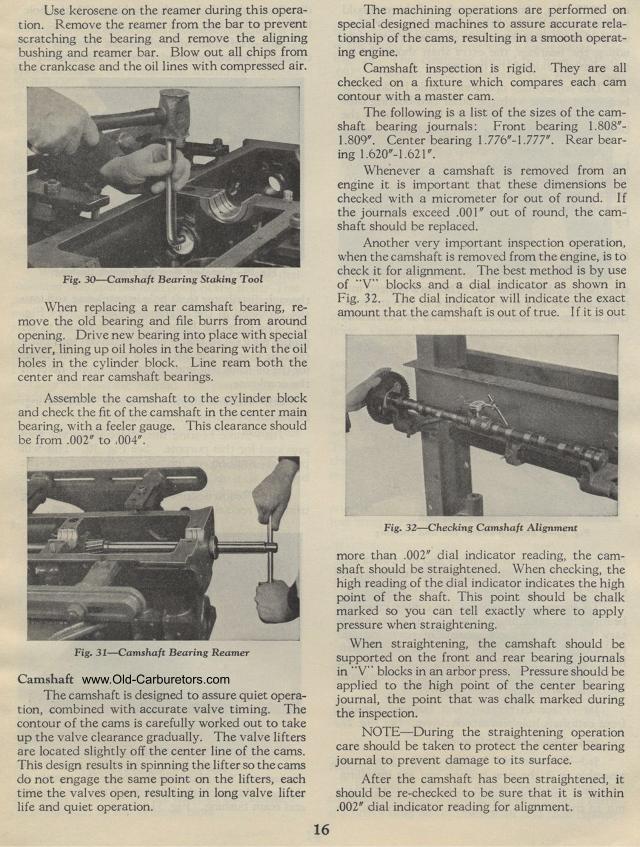
Another very important inspection operation, when the camshaft
is removed from the engine, is to check it for alignment. The best
method is by use of "V" blocks and a dial indicator as
shown in Fig. 32. The dial indicator will indicate the exact amount
that the camshaft is out of true. I f it is out
Fig. 32— Checking Camshaft Alignment
more than .002" dial indicator reading, the cam-shaft should
be straightened. When checking, the high reading of the dial indicator
indicates the high point of the shaft. This point should be chalk
marked so you can tell exactly where to apply pressure when straightening.
When straightening, the camshaft should be supported on the front
and rear bearing journals in "V" blocks in an arbor press.
Pressure should be applied to the high point of the center bearing
journal, the point that was chalk marked during the inspection.
NOTE— During the straightening operation care should be taken
to protect the center bearing journal to prevent damage to its
surface.
After the camshaft has been straightened, it should be re-checked
to be sure that it is within .002" dial indicator reading
for alignment.