Skip to: site menu | section menu | main content
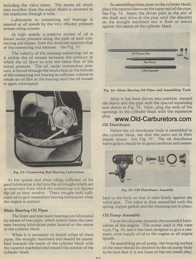
In assembling these pipes to the cylinder block, place the tapered sleeve on the taper end of the pipe. See Fig. 54. Insert the driver pilot in the end of the shaft and drive in the pipe until the shoulder on the straight machined end is flush or seated against the center of the cylinder block.
Oil Pressure Pipe Collar Plug
Pipe Driver
Collor Expander
Fig. 54— Main Bearing Oil Pipes and Assembling Tools
After it has been driven into position, expand the sleeve and the
pipe with the special expanding tool shown in Fig. 54. Next, plug
the ends of the openings in the cylinder block with the expansion
plug.
Oil Distributor
Before the oil distributor body is assembled to the cylinder block,
see that the parts are in their proper places. See Fig. 55. The
oil distributor valve gasket should be in good condition and assem-
bled to the body so that it rests firmly against the valve seat.
The valve is then assembled with the spring, copper gasket and
the retaining nut in place.
Oil Pump Assembly
Upon the oil pump depends the successful lubrication of the engine.
The pump used is the vane type, Fig. 56, and it has been designed
to give a constant, even supply of oil to the engine at all engine
speeds.
In assembling an oil pump, the bearing surface of the rotor should
be checked in the oil pump body to be sure that it is not loose
or has too much play,
Fig. 55— Oil Distributor Assembly
including the valve stems. The excess oil which may overflow from
the rocker shafts is returned to the crankcase through a tube.
Lubrication to connecting rod bearings is assured at all speeds
by the very efficient pressure stream oiling system.
At high speeds, a positive stream of oil is forced under pressure
along the path of each connecting rod dipper, from the direction
opposite that of the connecting rod rotation. See Fig. 53.
The velocity of the rotating connecting rod as it strikes the oil
stream increases the pressure at which the oil flows to over ten
times that of the initial pressure. The oil, under tremendous pressure,
is forced through the intake hole at the bottom of the connecting
rod bearing in sufficient volume to retain an oil film in the bearing
until the oil stream is again intercepted.
Fig. 53— Connecting Rod Bearing Lubrication
At low speeds and when idling, sufficient oil for good lubrication
is fed into the oil troughs which act as reservoirs from which
the connecting rod dippers dip oil as they revolve. These troughs
hold sufficient oil to give immediate bearing lubrication when
the engine is started.
Main Bearing Oil Pipes
The front and rear main bearings are lubricated by means of two
pipes, which extend from the common bearing lubrication point
located at the center of the cylinder block.
When it is necessary to install either of these pipes, the straight
machined end should be assembled towards the inside of the cylinder
block with the tapered machined end toward the outside of the cylinder
block.