Skip to: site menu | section menu | main content
of each of these smaller pipes is securely held in its trough and acts as a nozzle directing its stream of oil at an angle into the dipper of the revolving connecting rod. This angle was carefully determined
Oil Pan Assembly
to insure that the connecting rod dipper will intercept the maximum amount of oil in the short time that it is passing the oil stream.
The vertical feed pipe is a seamless steel tube, while the two
connecting pipes and the smaller relay pipes are made of double
walled tinned brass tubing. They are sweated with leak-proof joints
to their respective relays. These relays are of brass and are securely
bolted in the assembly. The oil drain is located in a more accessible
position at the left side of the oil pan.
Whenever an oil pan is removed from an engine, or a new oil pan
is installed, it should be thoroughly cleaned, the height of the
troughs and the position of the oil nozzles checked.
The oil pan trough gauge, shown in Fig. 58, is used to check the
distance from the flange of the oil pan to the top of the sides
of the troughs. The gauge cross bar is rested on the flange, with
gaskets
Fig. 58— Oil Trough Gauge
removed, and the rod in the center of the gauge should just clear
the sides of the troughs. If it does not, the trough should either
be raised or lowered until it does. It is likewise important that
the oil
as excessive clearance at this point will reduce the pressure of
the pump.
Check clearance between the shaft and oil pump body. This should
not exceed .009". If it exceeds, replacement is the only remedy.
The rotor is assembled into the body with the two blades and springs.
The taper end of the oil pump blade must be in the direction of
pump rotation.
The cover and cover gasket is assembled to the body, being sure
that the oil inlet hole in both the cover and the gasket is in
line with the oil inlet hole in the body of the oil pump. Fig.
56.
Screen Cover
Fig. 56— Oil Pump Assembly
The oil pump screen cover is placed in position and the oil inlet
pipe is assembled in place, thus holding the cover in position.
Next the screen is assembled and held in place with the retainer
spring.
In securing oil pump assembly to the cylinder block, be sure that
the oil pump set screw is fully seated and then locked by means
of the lock nut. The taper on this set screw fits into a tapered
hole in the oil pump body and centers the oil pump body between
the throws of the crankshaft.
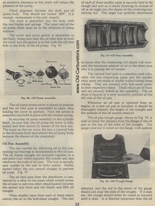
Oil Pan Assembly
The new system for delivering oil to the connecting rod bearings
is incorporated in the oil pan. The oil dipper troughs are stamped
together in a one-piece tray which supports the system and also
reinforces the walls of the pan. The tray is securely spot welded
in the pan at forty points. Baffles extend below the two central
troughs to prevent oil surge. Fig. 57.
The oil feed pipe from the distributor is connected by a relay
to two pipes which extend across the oil pan to join two other
relays located between the second and third and the fourth and
fifth oil troughs.
Three smaller pipes from each of these relays convey the oil to
the individual troughs. The end