Skip to: site menu | section menu | main content
Whenever a crankshaft has been removed from an engine, it is important that these dimensions be checked with a micrometer for out of round, taper and undersize. If the journals exceed .001" out of round or taper, the crankshaft should be replaced. Slightly undersize journals can be used providing that they are within the above limits for out of round or taper.
Another very important inspection operation, when the crankshaft is removed from the engine, is to check it for alignment. The best method is by use of "V" blocks and a dial indicator as shown in Fig. 23. The dial indicator will indicate the exact amount that the crankshaft is out of true. If it is out more than .002" dial indicator reading, the crankshaft should be straightened.
If center bearing is out of round, due to wear,
some judgment must be used in making this check.
When checking, the high reading of the dial
indicator indicates the high point of the shaft. This
point should be chalk marked so that you can tell
exactly where pressure should be applied when
straightening. Straightening can be done by sup-
porting the crankshaft on the front and rear main
bearing journals on "V" blocks in the arbor press.
Pressure should be applied on the high side of the
center main bearing journal, the point that was
chalk marked during the inspection operation.
NOTE: An old main bearing should be used to protect the center
main bearing journal during this operation.
After the crankshaft has been straightened, it should be re-checked
to be sure that it is within .002" dial indicator reading
for straightness.
Installing Crankshaft
Wipe out all of the bearing surfaces in the cylinder block and
the bearing caps as well as the
Fig. 24— Crankshaft End Play
crankshaft journals. Oil the bearings and assemble the crankshaft
to the cylinder block.
14
Check the end play by forcing the crankshaft to its extreme rear
position. Check at the rear side of the center main bearing with
a feeler gauge. See Fig. 24. This clearance should be from .004" to
.007". NOTE:— Our experience has shown that
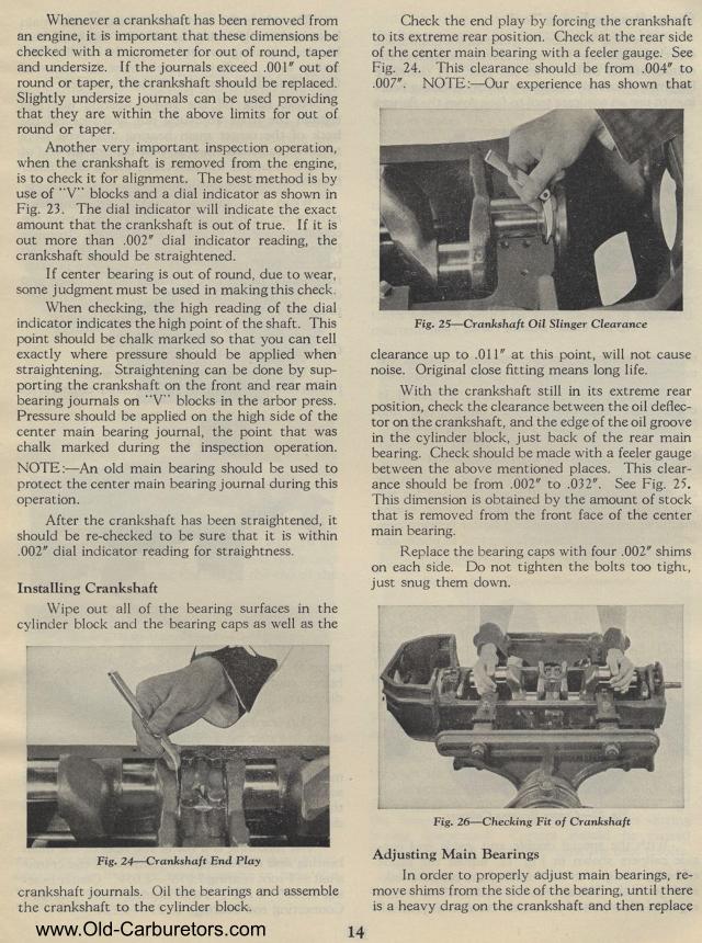
Fig. 25— Crankshaft Oil Slinger Clearance
clearance up to .011" at this point, will not cause noise.
Original close fitting means long life.
With the crankshaft still in its extreme rear position, check the
clearance between the oil deflector on the crankshaft, and the
edge of the oil groove in the cylinder block, just back of the
rear main bearing. Check should be made with a feeler gauge between
the above mentioned places. This clearance should be from .002" to
.032". See Fig. 25. This dimension is obtained by the amount
of stock that is removed from the front face of the center main
bearing.
Replace the bearing caps with four .002" shims on each side.
Do not tighten the bolts too tight, just snug them down.
Fig. 26— Checking Fit of Crankshaft
Adjusting Main Bearings
In order to properly adjust main bearings, re-move shims from the
side of the bearing, until there is a heavy drag on the crankshaft
and then replace