Skip to: site menu | section menu | main content
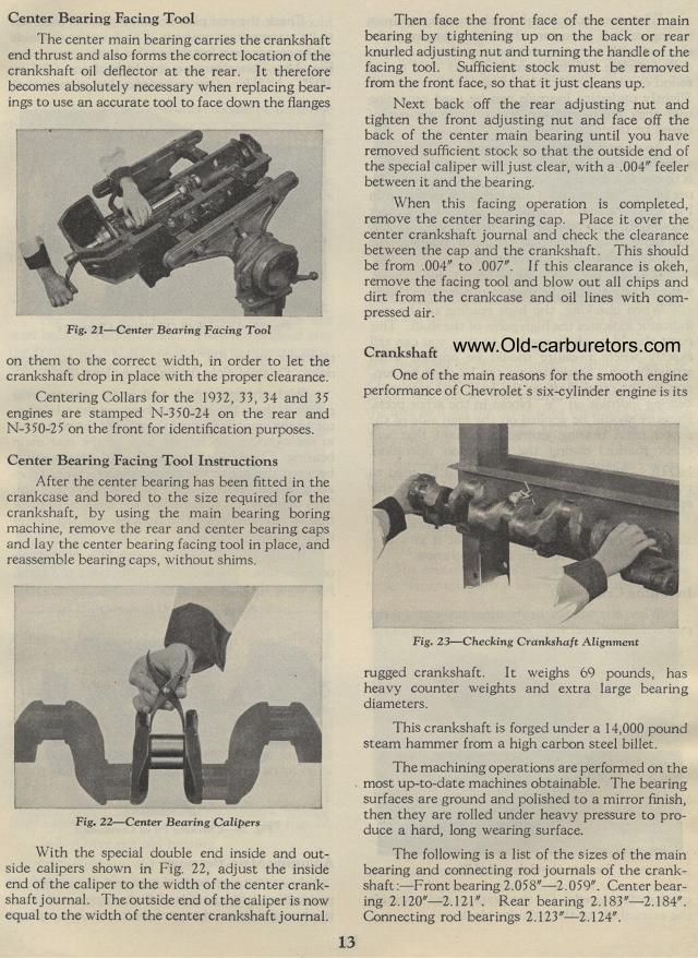
Center Bearing Facing Tool
The center main bearing carries the crankshaft end thrust and also forms the correct location of the crankshaft oil deflector at the rear. It therefore becomes absolutely necessary when replacing bearings to use an accurate tool to face down the flanges
Fig. 21— Center Bearing Facing Tool
on them to the correct width, in order to let the crankshaft drop
in place with the proper clearance.
Centering Collars for the 1932, 33, 34 and 35 engines are stamped
N-350-24 on the rear and N-350-25 on the front for identification
purposes.
Center Bearing Facing Tool Instructions
After the center bearing has been fitted in the crankcase and bored
to the size required for the crankshaft, by using the main bearing
boring machine, remove the rear and center bearing caps and lay
the center bearing facing tool in place, and reassemble bearing
caps, without shims.
Fig. 22— Center Bearing Calipers
With the special double end inside and out-side calipers shown
in Fig. 22, adjust the inside end of the caliper to the width of
the center crank-shaft journal. The outside end of the caliper
is now equal to the width of the center crankshaft journal.
13
Then face the front face of the center main bearing by tightening
up on the back or rear knurled adjusting nut and turning the handle
of the facing tool. Sufficient stock must be removed from the front
face, so that it just cleans up.
Next back off the rear adjusting nut and tighten the front adjusting
nut and face off the back of the center main bearing until you
have removed sufficient stock so that the outside end of the special
caliper will just clear, with a .004" feeler between it and
the bearing.
When this facing operation is completed, remove the center bearing
cap. Place it over the center crankshaft journal and check the
clearance between the cap and the crankshaft. This should be from
.004" to .007". If this clearance is okeh, remove the
facing tool and blow out all chips and dirt from the crankcase
and oil lines with compressed air.
Crankshaft
One of the main reasons for the smooth engine performance of Chevrolet's
six-cylinder engine is its
Fig. 23— Checking Crankshaft Alignment
rugged crankshaft. It weighs 69 pounds, has heavy counter weights
and extra large bearing diameters.
This crankshaft is forged under a 14,000 pound steam hammer from
a high carbon steel billet.
The machining operations are performed on the most up-to-date machines
obtainable. The bearing surfaces are ground and polished to a mirror
finish, then they are rolled under heavy pressure to pro-duce a
hard, long wearing surface.
The following is a list of the sizes of the main bearing and connecting
rod journals of the crank-shaft :—Front bearing 2.058"—2.059".
Center bearing 2.120"—2.121". Rear bearing 2.183"—2.184".
Connecting rod bearings 2.123"—2.124".
