Skip to: site menu | section menu | main content
Crankcase Front End Plate
This part is assembled to the cylinder block with from one to three
gaskets. The reason for the various number of gaskets is to give
the correct alignment to the timing gears.
In assembling this part to the cylinder block, first use two gaskets
and hold in place with three screws. Then place a new camshaft
thrust plate over the camshaft hole in the end plate. Using a scale
laid against the thrust plate and over to the shoulder on the crankshaft
for the timing gear, check to see whether or not these two surfaces
are flush. Fig. 33. If the scale strikes the shoulder, on the crankshaft,
add another gasket. I f there is
Fig. 33— Checking Alignment of Timing Gears
space between the scale and the shoulder on the crankshaft, remove
one gasket.
After the proper number of gaskets have been installed between
the plate and the crankcase, assemble the screws and bolts, setting
the screws with a center punch.
Crankshaft and Camshaft Gears (Timing Gears)
The gear on the end of the crankshaft, or the crankshaft timing
gear, is cut from a solid piece of steel. It is a drive fit on
the end of the crankshaft as well as being held in place with a
key.
To properly remove this gear, without damage to it, a gear puller,
such as is shown in Fig. 34, is necessary. To replace this gear,
a driver is essential so that the gear can be driven straight back
on its seat accurately.
The camshaft gear, or camshaft timing gear, is a Bakelite and fabric
gear which has been pressed into gear blanks under enormous pressure.
After this blank has been made, the teeth and the inside hole of
the gear is machined, the timing mark punched on it and the keyway
cut. This gear together with the steel crankshaft gear gives long,
quiet, trouble free life.
17
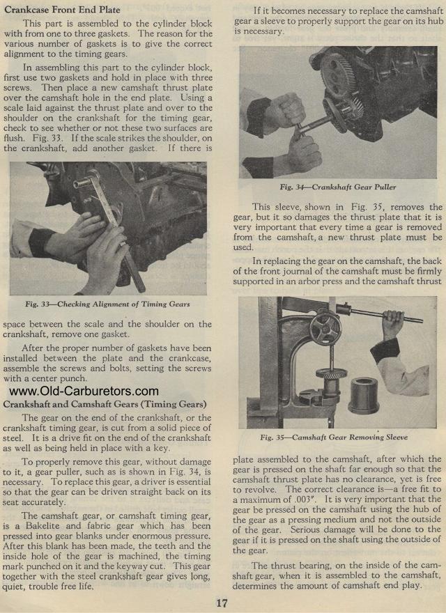
If it becomes necessary to replace the camshaft gear a sleeve to
properly support the gear on its hub is necessary.
Fig. 34— Crankshaft Gear Puller
This sleeve, shown in Fig. 35, removes the gear, but it so damages
the thrust plate that it is very important that every time a gear
is removed from the camshaft, a new thrust plate must be used.
In replacing the gear on the camshaft, the back of the front journal
of the camshaft must be firmly supported in an arbor press and
the camshaft thrust
Fig. 35— Camshaft Gear Removing Sleeve
plate assembled to the camshaft, after which the gear is pressed
on the shaft far enough so that the camshaft thrust plate has no
clearance, yet is free to revolve. The correct clearance is a free
fit to a maximum of .003". It is very important that the gear
be pressed on the camshaft using the hub of the gear as a pressing
medium and not the outside of the gear. Serious damage will be
done to the gear if it is pressed on the shaft using the outside
of the gear.
The thrust bearing, on the inside of the cam-shaft gear, when it
is assembled to the camshaft, determines the amount of camshaft
end play.