Skip to: site menu | section menu | main content
front end of the crankshaft, and eight banks of leaf springs,
each bank consisting of thirteen leaves, mounted in pairs in the
flyweight. Each pair of spring banks form a non-rigid unit through
which the pins drive this flyweight.
When the engine is running, any change in speed of the crankshaft, which would
cause vibration, will be resisted by the action of the flyweight in the balancer.
This resistance is manifested by a bending action in the four banks of springs
driven by the pins. These springs then tend to return to normal and in so doing
produce a bend in the four banks of springs on the opposite side of the pins.
Fig. 44— Harmonic Balancer Puller and Driver
This cycle of operation, acting directly opposite to the crankshaft
cycle thereby dampens out crank-shaft vibration.
Due to the construction of the balancer the component parts will
not be serviced separately.
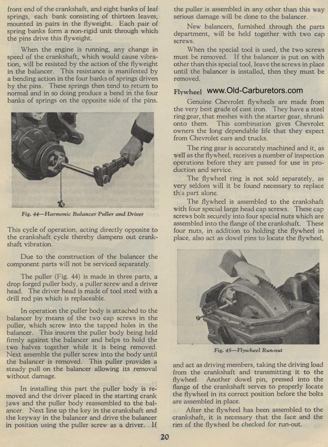
The puller (Fig. 44) is made in three parts, a drop forged puller
body, a puller screw and a driver head. The driver head is made
of tool steel with a drill rod pin which is replaceable.
In operation the puller body is attached to the balancer by means
of the two cap screws in the puller, which screw into the tapped
holes in the balancer. This insures the puller body being held
firmly against the balancer and helps to hold the two halves
together while it is being removed. Next assemble the puller
screw into the body until the balancer is removed. This puller
provides a steady pull on the balancer allowing its removal without
damage.
In installing this part the puller body is re-moved and the driver
placed in the starting crank jaws and the puller body reassembled
to the balancer. Next line up the key in the crankshaft and the
keyway in the balancer and drive the balancer in position using
the puller screw as a driver. If
20the puller is assembled in any other than this way serious
damage will be done to the balancer.
New balancers, furnished through the parts department, will be
held together with two cap screws.
When the special tool is used, the two screws must be removed.
I f the balancer is put on with other than this special tool,
leave the screws in place until the balancer is installed, then
they must be removed.
Flywheel
Genuine Chevrolet flywheels are made from the very best grade of
cast iron. They have a steel ring gear, that meshes with the
starter gear, shrunk onto them. This combination gives Chevrolet
owners the long dependable life that they expect from Chevrolet
cars and trucks.
The ring gear is accurately machined and it, as well as the flywheel,
receives a number of inspection operations before they are passed
for use in production and service.
The flywheel ring is not sold separately, as very seldom will it
be found necessary to replace this part alone.
The flywheel is assembled to the crankshaft with four special large
head cap screws. These cap screws bolt securely into four special
nuts which are assembled into the flange of the crankshaft. These
four nuts, in addition to holding the flywheel in place, also act
as dowel pins to locate the flywheel,
Fig. 45— Flywheel Run-out
and act as driving members, taking the driving load from the crankshaft
and transmitting it to the flywheel. Another dowel pin, pressed
into the flange of the crankshaft serves to properly locate the
flywheel in its correct position before the bolts are assembled
in place.
After the flywheel has been assembled to the crankshaft, it is
necessary that the face and the rim of the flywheel be checked
for run-out.