Skip to: site menu | section menu | main content
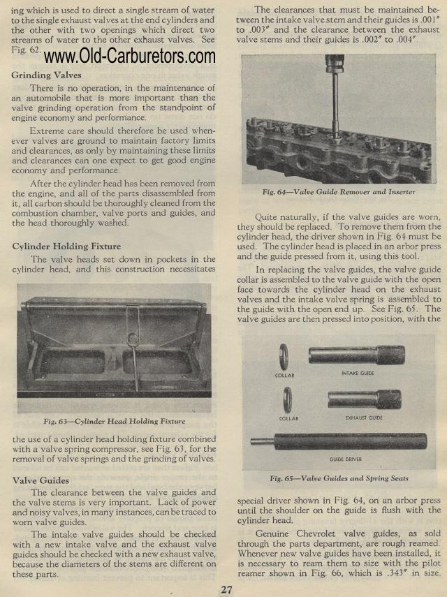
The clearances that must be maintained between the intake valve stem and their guides is .001" to .003" and the clearance between the exhaust valve stems and their guides is .002" to .004"
Valve Guide Remover and Inserter
Quite naturally, if the valve guides are worn, they should be replaced.
To remove them from the cylinder head, the driver shown in Fig.
61 must be used. The cylinder head is placed in an arbor press
and the guide pressed from it, using this tool.
In replacing the valve guides, the valve guide collar is assembled
to the valve guide with the open face towards the cylinder head
on the exhaust valves and the intake valve spring is assembled
to the guide with the open end up. See Fig. 65. The valve guides
are then pressed into position, with the
COLLAR COLLAR
Fig. 65— Valve Guides and Spring Seats
special driver shown in Fig. 64, on an arbor press until the shoulder
on the guide is flush with the cylinder head.
Genuine Chevrolet valve guides, as sold through the parts department,
are rough reamed. Whenever new valve guides have been installed,
it is necessary to ream them to size with the pilot reamer shown
in Fig. 66, which is .343" in size.
ing which is used to direct a single stream of water to the single
exhaust valves at the end cylinders and the other with two openings
which direct two streams of water to the other exhaust valves.
See Fig. 62.
Grinding Valves
There is no operation, in the maintenance of an
automobile that is more important than the valve grinding operation
from the standpoint of engine economy and performance.
Extreme care should therefore be used when-ever valves are ground
to maintain factory limits and clearances, as only by maintaining
these limits and clearances can one expect to get good engine economy
and performance.
After the cylinder head has been removed from the engine, and all
of the parts disassembled from it, all carbon should be thoroughly
cleaned from the combustion chamber, valve ports and guides, and
the head thoroughly washed.
Cylinder Holding Fixture
The valve heads set down in pockets in the cylinder head, and this
construction necessitates
Fig. 63— Cylinder Head Holding Fixture
the use of a cylinder head holding fixture combined with a valve
spring compressor, see Fig. 63, for the removal of valve springs
and the grinding of valves.
Valve Guides
The clearance between the valve guides and the valve stems is very
important. Lack of power and noisy valves, in many instances, can
be traced to worn valve guides.
The intake valve guides should be checked with a new intake valve
and the exhaust valve guides should be checked with a new exhaust
valve, because the diameters of the stems are different on these
parts.
