Skip to: site menu | section menu | main content
coil wire terminals to see that they are clean and tight in their
sockets. Clean or, if necessary, replace.
Reassemble the rotor, distributor cap, spark plug wires and coil wires.
Octane Selector— Passenger Cars
Checking and Setting Igniting Timing
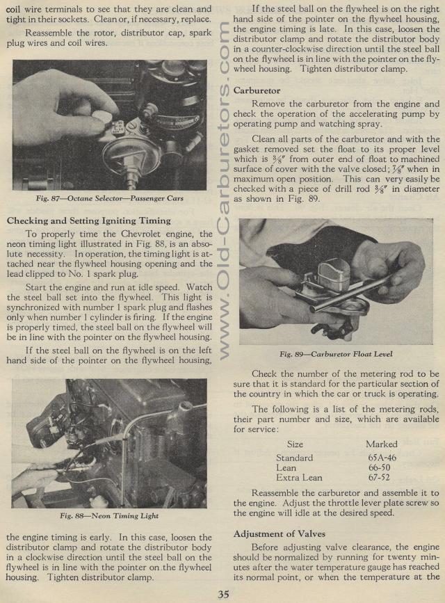
To properly time the Chevrolet engine, the neon timing light illustrated
in Fig. 88, is an absolute necessity. In operation, the timing
light is attached near the flywheel housing opening and the lead
clipped to No. 1 spark plug.
Start the engine and run at idle speed. Watch the steel ball set
into the flywheel. This light is synchronized with number 1 spark
plug and flashes only when number 1 cylinder is firing. If the
engine is properly timed, the steel ball on the flywheel will be
in line with the pointer on the flywheel housing.
I f the steel ball on the flywheel is on the left hand side of
the pointer on the flywheel housing,
Fig. 88— Neon Timing Light
the engine timing is early. In this case, loosen the distributor
clamp and rotate the distributor body in a clockwise direction
until the steel ball on the flywheel is in line with the pointer
on the flywheel housing. Tighten distributor clamp.
35
If the steel ball on the flywheel is on the right hand side of
the pointer on the flywheel housing, the engine timing is late.
In this case, loosen the distributor clamp and rotate the distributor
body in a counter-clockwise direction until the steel ball on the
flywheel is in line with the pointer on the fly-wheel housing.
Tighten distributor clamp.
Carburetor
Remove the carburetor from the engine and check the operation of
the accelerating pump by operating pump and watching spray.
Clean all parts of the carburetor and with the gasket removed set
the float to its proper level which is %" from outer end of
float to machined surface of cover with the valve closed; %" when
in maximum open position. This can very easily be checked with
a piece of drill rod %" in diameter as shown in Fig. 89.
Fig. 89— Carburetor Float Level
Check the number of the metering rod to be sure that it is standard
for the particular section of the country in which the car or truck
is operating.
The following is a list of the metering rods, their part number
and size, which are available for service:
Size Marked
Standard 65A-46
Lean 66-50
Extra Lean 67-52
Reassemble the carburetor and assemble it to the engine. Adjust
the throttle lever plate screw so the engine will idle at the desired
speed.
Adjustment of Valves
Before adjusting valve clearance, the engine should be normalized
by running for twenty minutes after the water temperature gauge
has reached its normal point, or when the temperature at the