Skip to: site menu | section menu | main content
Assemble the piston and connecting rod assembly to the alignment fixture, shown in Fig. 48, and check with the "V" block resting against the piston skirt to see that the rod and piston are in alignment. Both pins on the "V" block should rest against the face of the plate on the fixture.
Fig. 47— Assembling Connecting Rod to Piston
The piston should be in the same alignment as the connecting rod
when this check is made.
NOTE— The connecting rod should never be clamped in a bench
vise when installing the piston to it as tightening the clamp screw
will likely twist the rod.
Fig. 48— Checking Connecting Rod and Piston Alignment Assembling
Piston and Connecting Rod Assembly to Engine
In production, both the rod and the cap are stamped with the number
of the cylinder to which they are to be assembled. The numbers
are stamped on the camshaft side. When the rods are being reassembled
they should be placed back into the same cylinder from which they
were removed and the stamped numbers should be placed on the camshaft
side.
The condition of the crank pins, on the crank-shaft, should be
checked when installing new rods.
Damaged crankpins can only be corrected by the installation of
a new shaft, as it is impossible to maintain rod bearings on a
damaged crankpin.
Lubricate either the piston or the cylinder and slip the pistons
back into the cylinder using extreme care. Do not force the rings
into the bore. Compress the rings with a ring compressor, similar
to the one shown in Fig. 14, until they enter the cylinders easily.
The gaps in the three rings should not be in a vertical line, neither
should there be any ring gap over the piston pin, as the gasses
could leak by more easily at this point. Therefore, it is desirable
to stagger the gaps so that they will be equally distant around
the circumference of the piston.
The connecting rod should be assembled to the cylinder bore with
the piston pin clamp bolt to the camshaft side of the engine.
Lubricate the cap and assemble it to the connecting rod with the
number of the cylinder, which is stamped on it, toward the camshaft
side and the
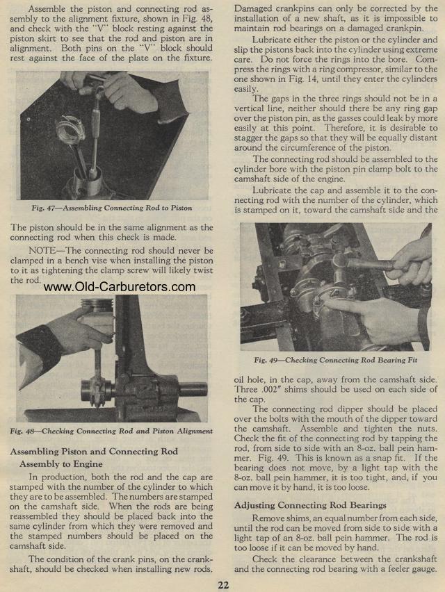
Fig. 49— Checking Connecting Rod Bearing Fit
oil hole, in the cap, away from the camshaft side. Three .002" shims
should be used on each side of the cap.
The connecting rod dipper should be placed over the bolts with
the mouth of the dipper toward the camshaft. Assemble and tighten
the nuts. Check the fit of the connecting rod by tapping the rod,
from side to side with an 8-oz. ball pein hammer. Fig. 49. This
is known as a snap fit. I f the bearing does not move, by a light
tap with the 8-oz. ball pein hammer, it is too tight, and, if you
can move it by hand, it is too loose.
Adjusting Connecting Rod Bearings
Remove shims, an equal number from each side, until the rod can
be moved from side to side with a light tap of an 8-oz. ball
pein hammer. The rod is too loose if it can be moved by hand.
Check the clearance between the crankshaft and the connecting rod
bearing with a feeler gauge.