Skip to: site menu | section menu | main content
Weak valve springs effect the economy and power of the engine; therefore, each time the valves of an engine are ground, the valve springs should be checked to be sure they have not been weakened from the heat of the engine. This can easily be done by comparing the springs removed with a new spring from parts stock. Any springs that do not match up with the new spring should be replaced with new genuine Chevrolet springs.
The valve spring is retained to the valve with a cup and a key. It is necessary to compress the spring with the spring compressor shown in Fig. 71, which is a part of the cylinder head holding fixture, far enough to allow the keys to be inserted in the valve stem
Fig. 71— Valve Spring Compressor
The valve springs are assembled with the close coiled end towards
the cylinder head.
Installing Cylinder Head Assembly
It is good practice to install a new cylinder head gasket each
time the cylinder head is removed
Fig. 72— Cylinder Head Guide Pins
to properly align the cylinder head to the cylinder block and keep
the cylinder head gasket in place and free from damage, the cylinder
head guide pins illustrated in Fig. 72 should be used.
30They screw into the cylinder block at the front and rear holes
on the manifold side and guide the head into position.
After the head has been properly aligned, insert and tighten the
cylinder head bolts with a wrench, tightening each one evenly a
little at a time in the order shown in the cylinder head bolt tightening
Fig. 73— Cylinder Head Bolt Tightening Diagram
diagram, Fig. 73. The order in which the bolts are tightened is important, as many water leaks between the cylinders are caused by other than this method.
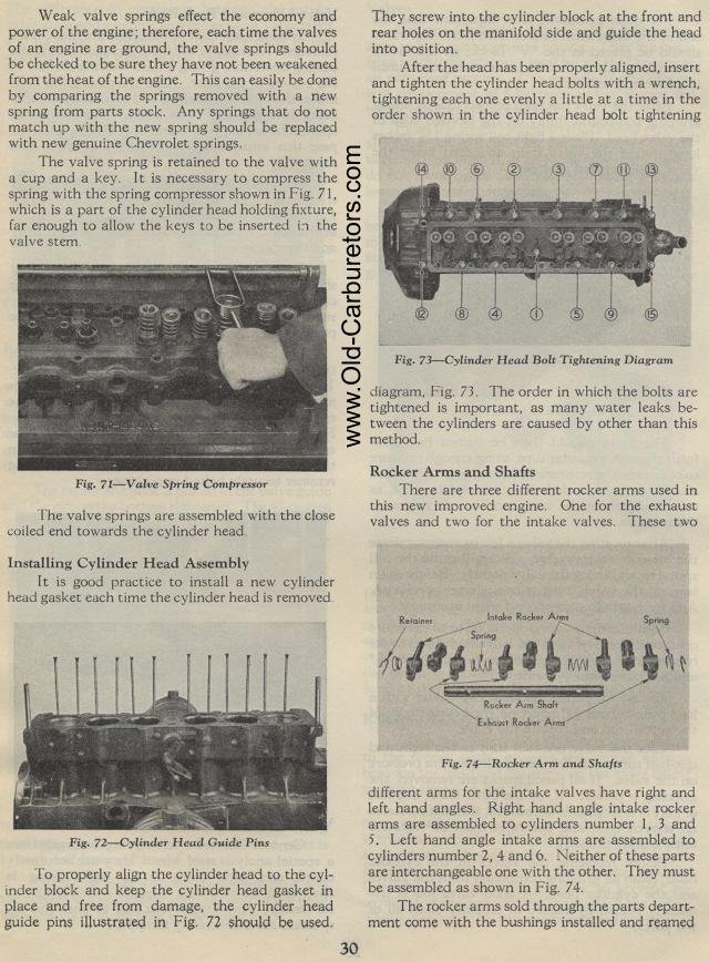
Rocker Arms and Shafts
There are three different rocker arms used in this new improved
engine. One for the exhaust valves and two for the intake valves.
These two
different arms for the intake valves have right and left hand angles.
Right hand angle intake rocker arms are assembled to cylinders
number 1, 3 and 5. Left hand angle intake arms are assembled to
cylinders number 2, 4 and 6. Neither of these parts are interchangeable
one with the other. They must be assembled as shown in Fig. 74.
The rocker arms sold through the parts department come with the
bushings installed and reamed