Skip to: site menu | section menu | main content
Valve Lifters and Push Rods
Genuine Chevrolet valve lifters are made from castings. The head of the lifter is chilled during the casting operation, giving a hard wearing surface to the bottom of the lifter. After the casting has been made, the lifter is machined and accurately ground, being held to very close limits. The inspection operations are very rigid and only those parts that pass this inspection are used in production and service.
The push rods are made from a solid piece of steel with the two
ends upset. The ends of the push rod are carefully machined to
give a smooth surface at the points where the rod contacts the
valve lifter and the rocker arm.
In assembling the valve lifter to the engine, it should be a free
fit, and the end that contacts the camshaft should be smooth. If
this end shows any signs of wear, it is good practice to replace
these parts.
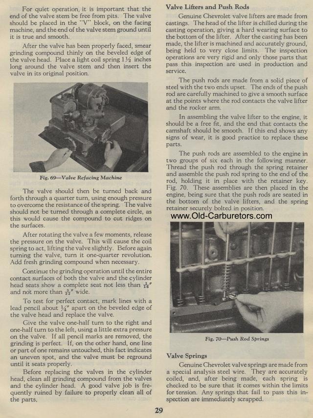
The push rods are assembled to the engine in two groups of six
each in the following manner. Thread the push rod through the spring
retainer and assemble the push rod spring to the end of the rod,
holding it in place with the retainer key. Fig. 70. These assemblies
are then placed in the engine, being sure that the push rods are
seated in the bottom of the valve lifters, and the spring retainer
securely bolted in position.
Fig. 70— Push Rod Springs
Valve Springs
Genuine Chevrolet valve springs are made from a special analysis
steel wire. They are accurately coiled, and, after being made,
each spring is checked to be sure that it comes within the limits
for tension. Any springs that fail to pass this inspection are
immediately scrapped.
For quiet operation, it is important that the end of the valve
stem be free from pits. The valve should be placed in the "V" block,
on the facing machine, and the end of the valve stem ground until
it is true and smooth.
After the valve has been properly faced, smear grinding compound
thinly on the beveled edge of the valve head. Place a light coil
spring 1 % inches long around the valve stem and then insert the
valve in its original position.
Fig. 69— Valve Refacing Machine
The valve should then be turned back and forth through a quarter
turn, using enough pressure to overcome the resistance of the spring.
The valve should not be turned through a complete circle, as this
would cause the compound to cut ridges on the surfaces.
After rotating the valve a few moments, release the pressure on
the valve. This will cause the coil spring to act, lifting the
valve slightly. Before again turning the valve, turn it one-quarter
revolution. Add fresh grinding compound when necessary.
Continue the grinding operation until the entire contact surfaces
of both the valve and the cylinder head seats show a complete seat
not less than is and not more than 332" wide.
To test for perfect contact, mark lines with a lead pencil about
%" apart on the beveled edge of the valve head and replace
the valve.
Give the valve one-half turn to the right and one-half turn to
the left, using a little extra pressure on the valve. I f all pencil
marks are removed, the grinding is perfect. If, on the other hand,
one sline or part of one remains untouched, this fact indicates
an uneven spot, and the valve must be reground until it seats properly.
Before replacing the valves in the cylinder head, clean all grinding
compound from the valves and the cylinder head. A good valve job
is frequently ruined by failure to properly clean all of the parts,