Skip to: site menu | section menu | main content
nozzles and oil distributor pipes be checked to be sure that they
are tight in the pan. This is extremely important because, if they
are loose, there might be a possibility of the soldered joints
working loose, resulting in the breaking down of the pressure in
the oil lines, with the result that sufficient oil might not reach
the connecting rod dippers.
After making sure that all oil pipes are tight in the pan, check the height of
the oil nozzles and pipes with the gauge shown in Fig. 59. The side of the gauge
marked "Front" should be towards the front of the oil pan with the
hook side engaging the oil pan rail. The end of the nozzles and the curve of
the oil pipes must clear the gauge.
Oil Nozzle Height Gauge
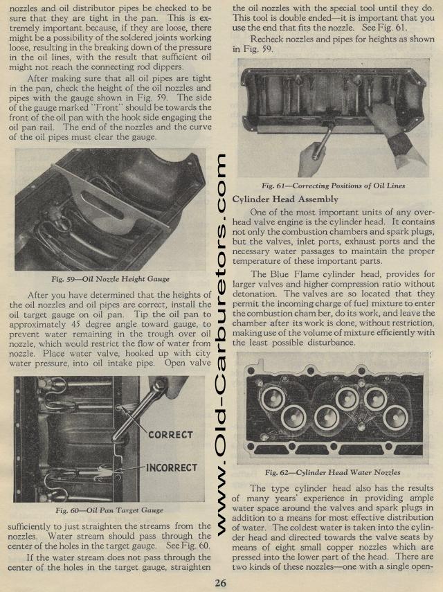
After you have determined that the heights of the oil nozzles and oil pipes are correct, install the oil target gauge on oil pan. Tip the oil pan to approximately 45 degree angle toward gauge, to prevent water remaining in the trough over oil nozzle, which would restrict the flow of water from nozzle. Place water valve, hooked up with city water pressure, into oil intake pipe. Open valve
Fig. 60— Oil Pan Target Gauge
sufficiently to just straighten the streams from the
nozzles. Water stream should pass through the
center of the holes in the target gauge. See Fig. 60,
If the water stream does not pass through the
center of the holes in the target gauge, straighten
26the oil nozzles with the special tool until they do. This tool
is double ended it is important that you use the end that fits
the nozzle. See Fig. 61.
Recheck nozzles and pipes for heights as shown in Fig. 59.
Fig. 61— Correcting Positions of Oil Lines Cylinder Head
Assembly
One of the most important units of any over-head valve engine is
the cylinder head. It contains not only the combustion chambers
and spark plugs, but the valves, inlet ports, exhaust ports and
the necessary water passages to maintain the proper temperature
of these important parts.
The Blue Flame cylinder head, provides for larger valves and higher
compression ratio without detonation. The valves are so located
that they permit the incoming charge of fuel mixture to enter the
combustion cham ber, do its work, and leave the chamber after its
work is done, without restriction, making use of the volume of
mixture efficiently with the least possible disturbance.
Fig. 62—Cylinder Head Water Nozzles
The type cylinder head also has the results of many years' experience
in providing ample water space around the valves and spark plugs
in addition to a means for most effective distribution of water.
The coldest water is taken into the cylinder head and directed
towards the valve seats by means of eight small copper nozzles
which are pressed into the lower part of the head. There are two
kinds of these nozzles—one with a single open-