Skip to: site menu | section menu | main content
if there is an excessive amount of end play in the camshaft, it
is necessary to remove the gear and shaft assembly and press the
gear further on the shaft so that the thrust plate is tight, yet
free to revolve, to a maximum of .003" clearance. See Fig.
36.
Fig. 36—Camshaft End Play
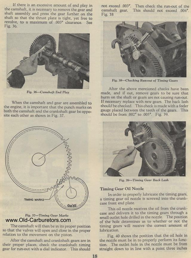
When the camshaft and gear are assembled to the engine, it is important that the punch marks on both the camshaft and the crankshaft gear be opposite each other as shown in Fig. 37.
Fig. 37— Timing Gear Marks
The camshaft will then be in its proper position so that the valves
will open and close in the proper relation to the movement on the
piston.
After the camshaft and crankshaft gears are in their proper places,
check the crankshaft timing gear for run-out with a dial indicator.
This should
18not exceed .003". Then check the run-out of the camshaft
gear. This should not exceed .004". Fig. 38
Fig. 38— Checking Run-out of Timing Gears
After the above mentioned checks have been made, and if out, remove
gears to be sure that burrs on the shaft or gears are not causing
run-out. If necessary replace with new gears. The back lash should
be checked. This check is made with a feeler gauge placed between
the teeth of the gears. This should be from .002" to .005".
Fig. 39.
Fig. 39— Timing Gear Back Lash
Timing Gear Oil Nozzle
In order to properly lubricate the timing gears, a timing gear
oil nozzle is screwed into the crank-case front end plate.
This oil nozzle receives the oil from the crank-case and delivers
it to the timing gears through a small outlet hole drilled in the
nozzle. The position of the hole determines as to whether or not
the timing gears will receive the correct amount of lubrication.
Fig. 40 shows the position that the oil hole in the nozzle must
be in to properly perform its function. The outlet hole in the
nozzle must be from straight down to in line with a point three
inches