Skip to: site menu | section menu | main content
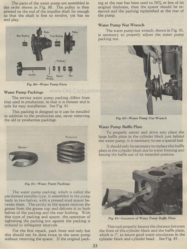
The parts of the water pump are assembled in the order shown in Fig. 80. The pulley is then pressed on the end of the impeller shaft far enough so that the shaft is free to revolve, yet has no end play.
Water Pump Parts
Water Pump Packings
The service water pump packing differs from that used in production,
in that it is thinner and is split for easy installation. See Fig.
81.
This packing is designed so it can be installed in addition to
the production one, never removing the old or production packings.
Production
Fig. 81— Water Pump Packings
The water pump packing, which is called the pre-formed metallic
type, is assembled in the pump body in two halves, with a pressed
steel spacer between them. The cavity in the spacer receives the
grease from the grease cup and delivers it to both halves of the
packing and the rear bushing. With this type of packing and spacer,
the operation of tightening the packing nut against the packing
is reduced to infrequent intervals.
For the first repack, pack front end only but this should not be
done twice in the same pump without removing the spacer. I f the
original pack-ing at the rear has been used to 50% or less of its
original thickness, then the spacer should be re-moved and the
packing replenished at the rear of the pump.
Water Pump Nut Wrench
The water pump nut wrench, shown in Fig. 82, is necessary to properly
adjust the water pump packing nut.
Fig. 82— Water Pump Nut Wrench Water Pump Baffle Plate
To properly center and drive into place the large baffle plate
in the cylinder block just behind the water pump, it is necessary
to use a special tool.
It should only be necessary to replace this baffle plate in the
cylinder block due to water freezing and forcing the baffle out
of its intended position.
Fig. 83— Location of Water Pump Baffle Plate
This tool properly locates the distance between the front of the
cylinder block and the baffle plate, which is 1', to insure good
water circulation in the cylinder block and cylinder head. See
Fig. 83.
Service