Skip to: site menu | section menu | main content
ready for assembly. Worn rocker arm bushings necessitate the replacement
of the rocker arms.
The rocker arm shafts are hollow and have holes drilled in them to allow oil
to pass into the rocker arm bushings. Worn rocker arm shafts should be replaced.
The rocker arms, springs and shaft supports are assembled to the rocker arm shafts
and locked in place with hair pin springs, in the order shown in Fig. 74.
One end of these shafts is plugged, and they must be installed to the cylinder head with the open ends to the center. After they are installed in their proper place, they should be held in position with the special bolt and the special washer. This special bolt allows the rocker arm and shaft assembly to be bolted in one place and the special washer prevents oil from leaking out around the bolt.
After the rocker arm and shaft assemblies are installed to the
cylinder head, assemble the spring to the brass coupling and then
place the elbow pipe onto this assembly. Compress the elbow pipe
back onto the spring and assemble the brass coupling to the end
of the shaft at the rear and allow the elbow pipe to come into
place in the front shaft. Then fasten the coupling nut onto the
end of the oil feed pipe.
Adjustment of Valves
Before adjusting valve clearance, the engine should be normalized
by running for twenty minutes after the water temperature gauge
has reached its normal point, or when the temperature at the rocker
arm shaft overflow has reached the point of 150 degrees Fahrenheit.
(Tighten all manifold bolts, valve rocker arm stud nuts, and cylinder
head bolts.)
Valve stems should be lubricated with light oil to make sure they
are not sticking —this is important.
Inlet valve clearance should be minimum .006" Hot.
Exhaust valve clearance should be minimum 013" Hot.
Vacuum Gauge
The vacuum gauge is used only to get the best idling. This method
of adjusting tappets makes corrections for variations in the
camshaft, and tappets may be noisy especially during the warm-up
period.
When the vacuum gauge is used, adjust to the highest Vacuum reading
with the
Inlet valve clearance not less than .006" Hot, nor more than
.008" Hot.
Exhaust valve clearance not less than .013" Hot, nor more
than .015" Hot.
In case of valve sticking slightly, the tappets will usually be
set very wide to offset this condition, so it is very necessary
that the valves be lubricated to prevent excessive valve lash and
noise, and consequent change of valve timing.
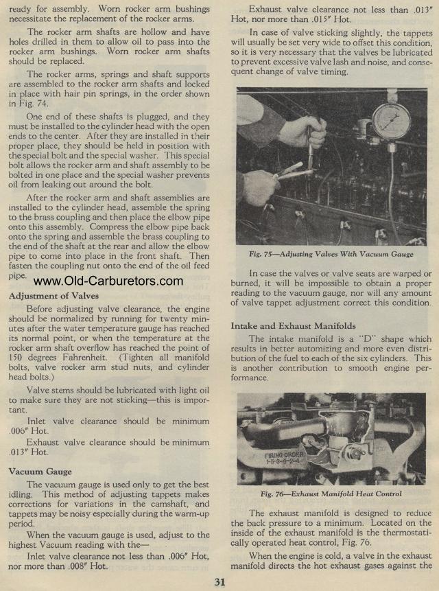
Fig. 75— Adjusting Valves With Vacuum Gauge
In case the valves or valve seats are warped or burned, it will
be impossible to obtain a proper reading to the vacuum gauge, nor
will any amount of valve tappet adjustment correct this condition.
Intake and Exhaust Manifolds
The intake manifold is a "D" shape which results in better
automizing and more even distribution of the fuel to each of the
six cylinders. This is another contribution to smooth engine performance.
Fig. 76— Exhaust Manifold Heat Control
The exhaust manifold is designed to reduce the back pressure to
a minimum. Located on the inside of the exhaust manifold is the
thermostatically operated heat control, Fig. 76.
When the engine is cold, a valve in the exhaust manifold directs
the hot exhaust gases against the