Skip to: site menu | section menu | main content
The difference in clearances between the intake valve stem and its guide and the exhaust valve stem and its guide is obtained by the differences in the diameters of the stems of the valves.
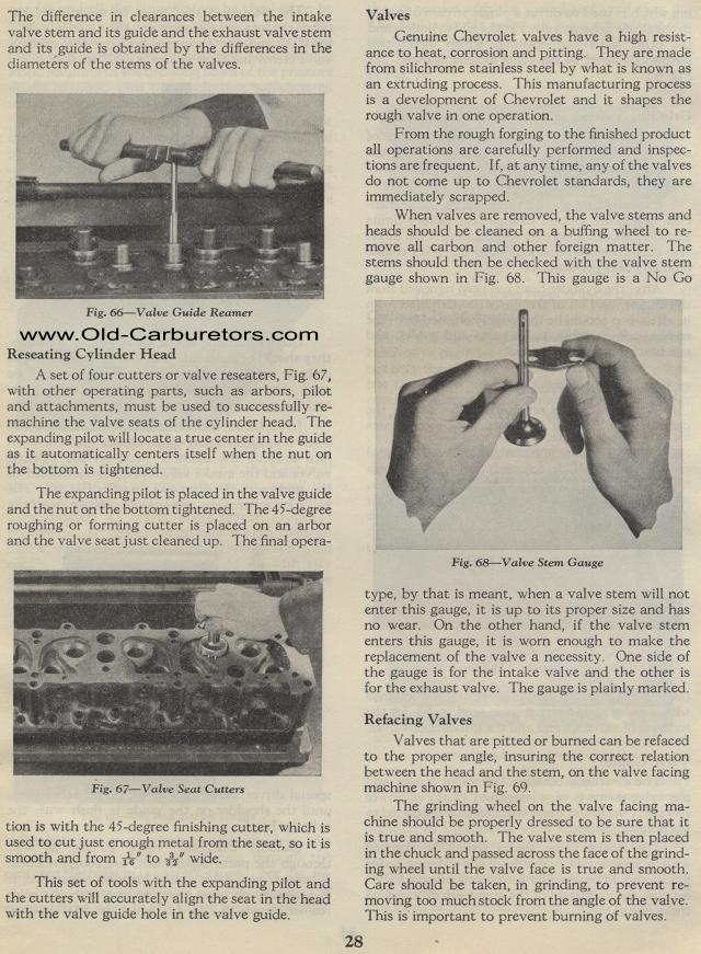
Valve Guide Reamer
Reseating Cylinder Head
A set of four cutters or valve reseaters, Fig. 67, with other operating
parts, such as arbors, pilot and attachments, must be used to successfully
re-machine the valve seats of the cylinder head. The expanding
pilot will locate a true center in the guide as it automatically
centers itself when the nut on the bottom is tightened.
The expanding pilot is placed in the valve guide and the nut on
the bottom tightened. The 45-degree roughing or forming cutter
is placed on an arbor and the valve seat just cleaned up. The final
opera-
Fig. 67— Valve Seat Cutters
tion is with the 45-degree finishing cutter, which is used to cut
just enough metal from the seat, so it is smooth and from 16" to
32" wide.
This set of tools with the expanding pilot and the cutters will
accurately align the seat in the head with the valve guide hole
in the valve guide.
28Valves
Genuine Chevrolet valves have a high resistance to heat, corrosion
and pitting. They are made from silichrome stainless steel by what
is known as an extruding process. This manufacturing process is
a development of Chevrolet and it shapes the rough valve in one
operation.
From the rough forging to the finished product all operations are
carefully performed and inspections are frequent. If, at any time,
any of the valves do not come up to Chevrolet standards, they are
immediately scrapped.
When valves are removed, the valve stems and heads should be cleaned
on a buffing wheel to re-move all carbon and other foreign matter.
The stems should then be checked with the valve stem gauge shown
in Fig. 68. This gauge is a No Go
Fig. 68— Valve Stem Gauge
type, by that is meant, when a valve stem will not enter this gauge,
it is up to its proper size and has no wear. On the other hand,
if the valve stem enters this gauge, it is worn enough to make
the replacement of the valve a necessity. One side of the gauge
is for the intake valve and the other is for the exhaust valve.
The gauge is plainly marked.
Refacing Valves
Valves that are pitted or burned can be refaced to the proper angle,
insuring the correct relation between the head and the stem,
on the valve facing machine shown in Fig. 69.
The grinding wheel on the valve facing ma-chine should be properly
dressed to be sure that it is true and smooth. The valve stem is
then placed in the chuck and passed across the face of the grinding
wheel until the valve face is true and smooth. Care should be taken,
in grinding, to prevent re-moving too much stock from the angle
of the valve. This is important to prevent burning of valves.